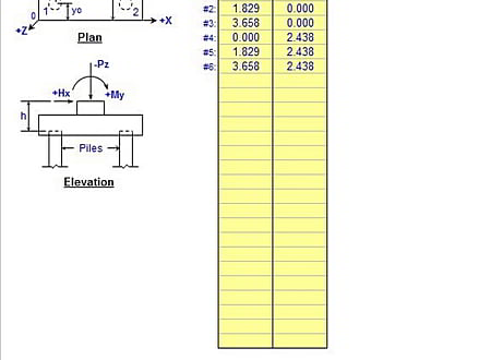
"PILEGRP" is a spreadsheet program written in MS-Excel for the purpose of analysis of pile groups with rigid caps using the "elastic method". Specifically, the properties of the pile group are calculated, and then based upon the applied vertical and horizontal loadings, the vertical and horizontal pile reactions are calculated. There is also a worksheet to check beam and punching shear in the pile cap for a single corner pile, for the purpose of estimating the required pile cap thickness and subsequent pile cap weight.
This workbook has some concrete design in them, based on the ACI 318-99 Code in their original form. To reflect the use of the ACI 318-05, I decided to give the user the option of selecting what ACI Code is desired to be used, 318-99, 318-02, or 318-05, in those specific worksheets. Once the user selects the desired ACI Code, the appropriate "phi" factors are displayed and used. One word of caution, be careful not to mix & match "phi" factors and load factors from the various concrete codes. It's obviously up to the user to be consistent. For the purpose of just what specific concrete analysis and design is done in this workbook, the selection of either ACI 318-02 or 318-05 gives the same results.
Program Assumptions and Limitations:
1. The Pile Group worksheets assume a minimum of 2 piles and a maximum of either 25, 75, 300, or 400 piles for a pile group.
2. This program uses the "elastic method" of analysis, assuming that the pile cap is in fact "rigid", so that the applied loads are linearly distributed among the piles. A common "rule-of-thumb" is to assume a pile cap thickness equal to least 1/10 of the longest dimension (length or width) of the pile cap. All piles are assumed to be vertical, and of equal size and length (stiffness). Battered piles are NOT permitted. The tops of all piles are assumed at the same level.
3. This program assumes an orthogonal X-Y-Z coordinate system. All piles and piers MUST BE located in the "positive" (1st) quadrant. "Negative" pile or pier/loading location coordinates are NOT permitted. "Right-Hand-Rule" sign convention is used for all applied forces and moments at pier locations.
4. The piles and piers/loadings can be numbered in any desired order. However, the user should make sure to either clear the contents of all spreadsheet cells that are not used for input or those cell values should be input = 0. All piles and piers/loadings MUST BE input in proper numerical sequence with no "breaks" in the numerical order of input data.
5. This program does NOT include the weight of the pile cap or piers in the calculation of the vertical pile reactions. However, the total weight of the pile cap and piers may be included by assuming an additional "ficticious" pier located at the centroid of the pile cap plan area, and applying the total weight at that "pier" location.
6. This program does NOT check the actual calculated pile reactions (vertical and horizontal) against known or given allowable pile reactions for downward, uplift, or lateral cases. This is done so that the extent of any acceptable overstress is left up to the judgement of the user. However, in all cases this must be checked by the user.
7. This program does NOT perform all of the necessary checks for the beam-type shear or punching shear for the pile cap, as this must be done independently by the user. However the "Corner Pile Shear" worksheet can be used to estimate the required pile cap thickness and subsequently the pile cap weight to be accounted for.
8. This program does NOT check the flexural requirements of the pile cap, as this must be done independently by the user.
9. This program contains numerous “comment boxes” which contain a wide variety of information including explanations of input or output items, equations used, data tables, etc. (Note: presence of a “comment box” is denoted by a “red triangle” in the upper right-hand corner of a cell. Merely move the mouse pointer to the desired cell to view the contents of that particular "comment box".)
* PILEGRP download link provides freeware version of the software.
Pile Capacity, Design Load Estimation and Pile Group Settlement
The GEMS – Pile Group Settlement Analysis software uses modern analytical techniques based on the subsurface soil profile, pile dimensions and group geometry to estimate the pile group settlement.
Analysis of 3D Pile Groups Under Combined Loadings
GROUP has been well accepted as an useful design tool for analyzing the behavior of piles in a group subjected to both axial and lateral loadings.
Portal and Gable Rigid Plane Frame Analysis
FRAME is a spreadsheet program written in MS-Excel for the purpose of plane frame analysis of portal and gable rigid plane frames subjected to various types of loading.
Pile Capacity Estimation, Axial and Lateral Load Analysis
The Comprehensive Pile Foundation Analysis (Land, Bridge & Waterfront Structures) software of GEMS provides feature rich & easy-to-use program modules for pile capacity estimation, axial and lateral load analysis.
Weld Group Analysis per AISC 9th Ed.
WELDGRP is a spreadsheet program written in MS-Excel for the purpose of analysis of weld groups using either the ultimate strength method or the elastic method.
Submit a review about PILEGRP software with your social media profile


No comments yet. Be the first to comment.